 |
TIPS |
|
TIPS |
CAD LOFTING
This is a small refinement to the tip on our CAD Lofting web page:
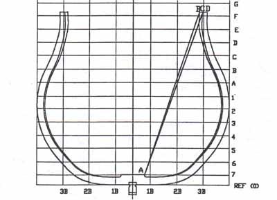
Draw the frame using Joes original AutoCAD procedure with the uniform frame thickness B - D. We prefer the thickness to be C - D at the top.
Draw straight line s A- B and A - C where A is any convenient point on the inside curve of the frame near the keel
Determine the angle between the two lines drawn in step 2. One method for this is to use the AutoCAD "angular dimension" command.
Use the AutoCAD rotate command to rotate the inner curve about point A through the angle determined in step 3. The rotated curve is the curved line from A to C in the drawing above.
Erase the curve from A to B and the two straight lines.
Use the AutoCAD mirror command to draw the other half of the frame